To get access to the system the user is required to provide username and password.
As per default, the machine has one superuser and one regular user profile. Both the profiles can use the machine, but the superuser has also access to the settings.
The default credentials are:
SUPERUSER
Username: admin
Password: 321Vision!
USER 2
Username: operator
Password: operator
Warning
PLEASE PROCEED TO CHANGE THE PASSWORDS FOR BOTH USERS AFTER FIRST LOGIN.
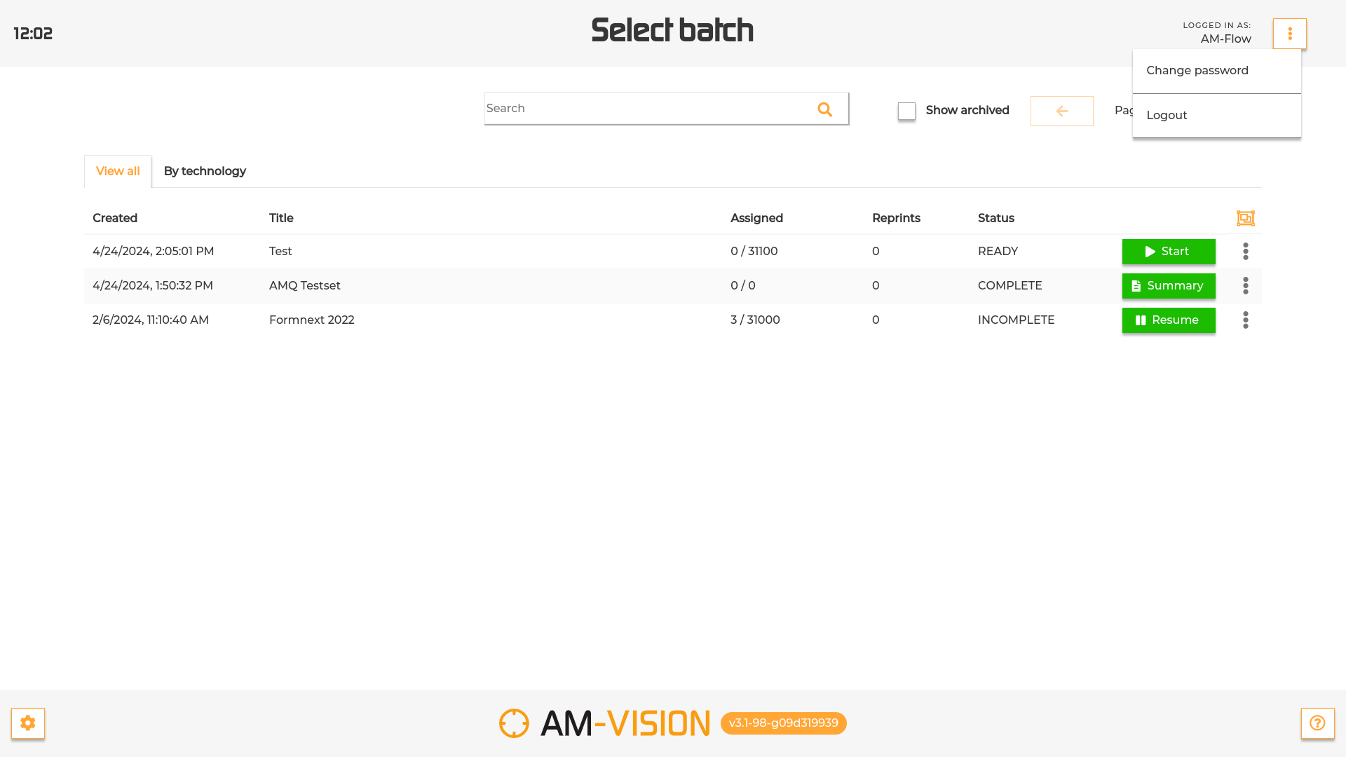
To change the password, press the button next to the “logged in as” in the top right corner of the homepage and select “Change Password” from the dropdown menu.
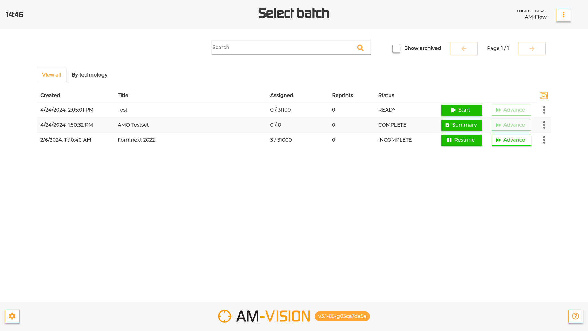
When logging in into the AM-Vision system, the operator is presented with a list of all the batches currently in the system.
For each batch, the table shows some key information, such as:
(1) Date and time of creation
(2) Title (Touch the screen on the corresponding area and scroll to the left to read the entire content in case of long names)
(3) Number of assigned parts
(4) Number of reprints (parts that were damaged and need to be reprinted)
(5) Status:
CREATED : the files within the batch are created, but still need to be rendered. In this status the batch is not ready to start the scanning session yet. To start the processing press ‘Process’ ().
PROCESSING: the rendering of the files is in progress. In this status the batch is not ready to start the scanning session yet. In the batch row it will be indicated the percentage of processing already done.
READY: all the parts within the batch have been rendered and the batch is ready to be scanned. To start scanning the batch press the ‘Start’ button.
INCOMPLETE : only part of the batch has been scanned. In this status the batch can be scanned. To keep scanning parts press the button ‘Resume’.
COMPLETE : all the objects within the batch are assigned to a scan. In this status the batch can no longer be scanned. Press the button ‘Summary’ to be redirected to the Summary page and have an overview of the batch content.
CONFLICTS : the amount of scans assigned to an object within the batch exceeds the maximum amount expected for that object. Press the Resolve button to solve the conflict and keep scanning.
If your machine configuration allows it, you can finalize a batch when is COMPLETE by pressing the “Finalize” button. This will mark the batch in your system as finalized.
If you machine configuration allows it, you can advance already assigned part by pressing the “Advance” button. If output grouping is enabled, you might be required to complete groups before advancing parts in case the batch contains any.
To inspect the content of a batch, press the three dots at the end of the batch row and select the option “Summary” from the menu.
To reset a batch, press the three dots and select the option “Reset batch” from the menu. A confirmation will be necessary as by selecting this option all the pending assignments will be permanently deleted.
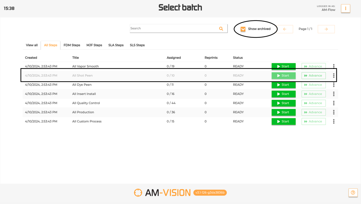
To hide a batch from the list, press the three dots and select the option “Archive batch” from the menu. In case of incomplete batches a confirmation will be necessary.
To display the hidden batches, select the “Show archived” checkbox next to the search bar (see image below).
To unarchive the batch simply open the pop up menu of the archived batch and select “Unarchive”.
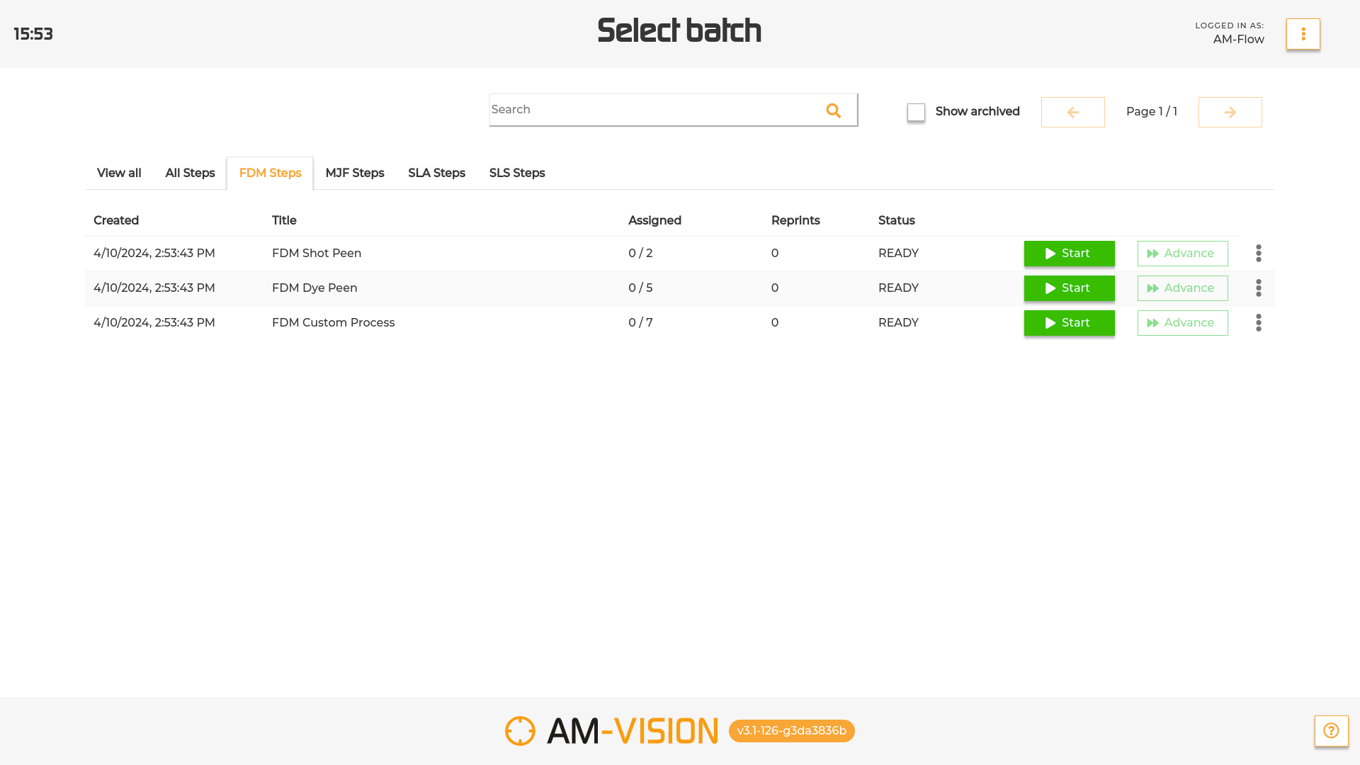
To filter the list of batches by their category, select the desired tab on top of the list.
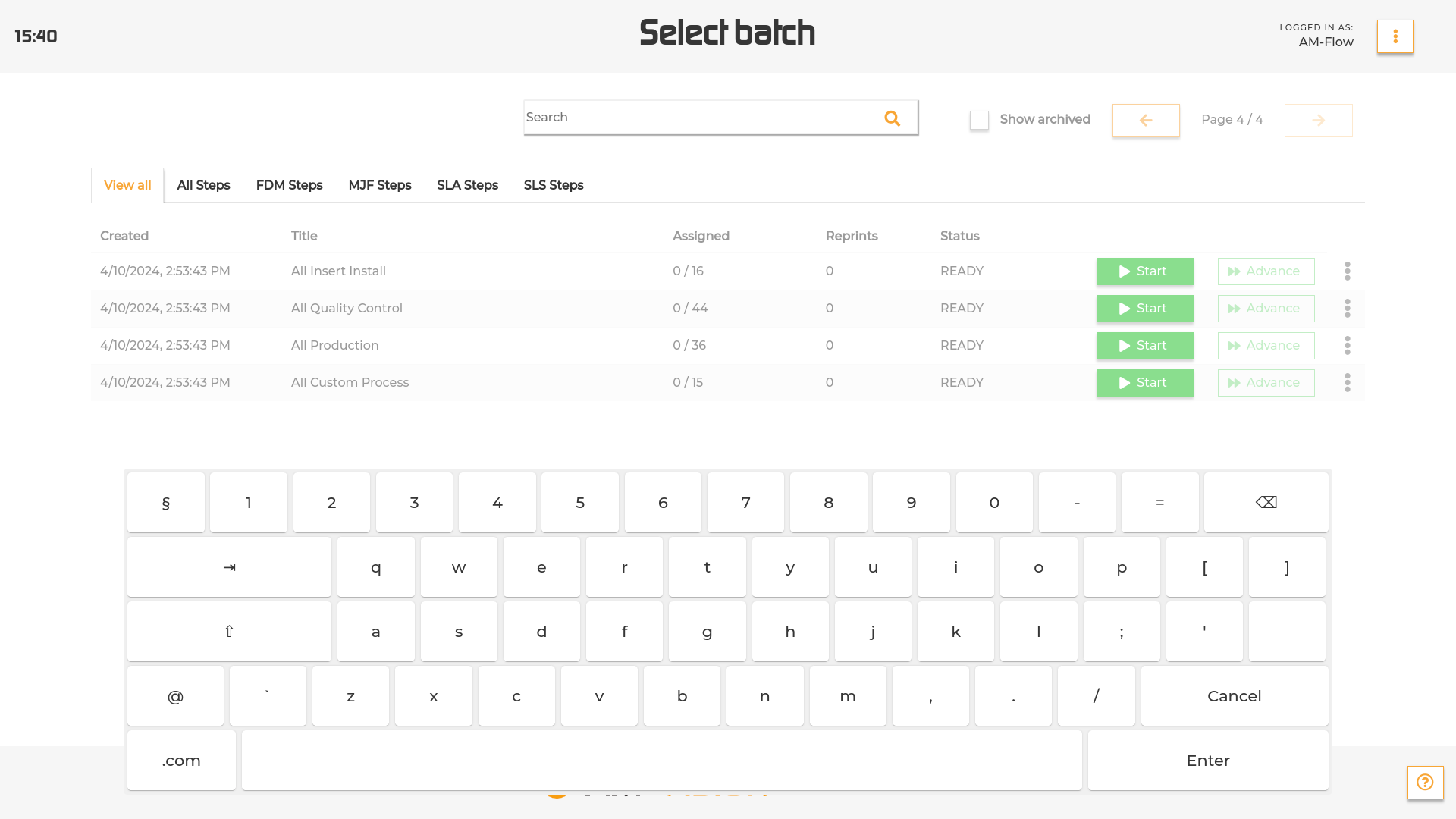
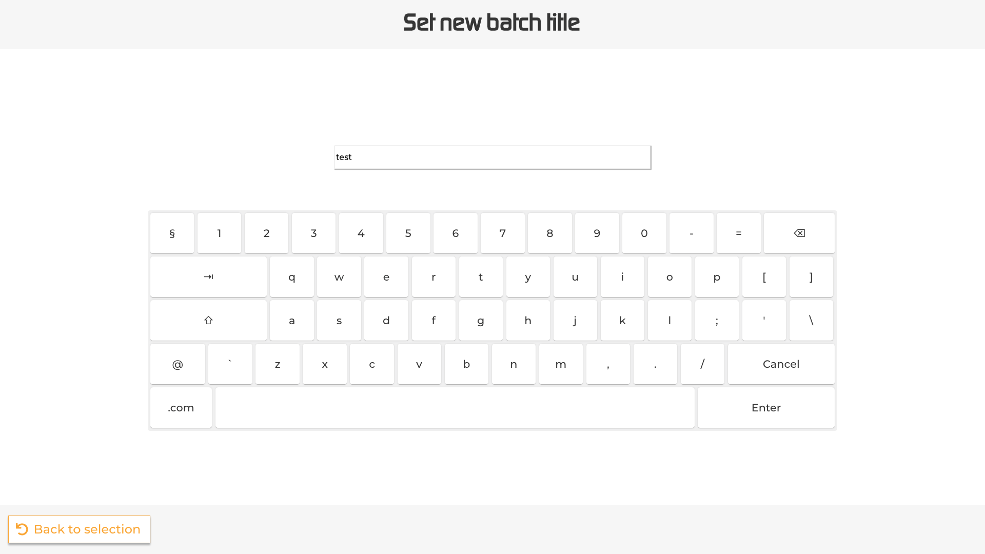
To search for a specific batch by title, tap the search bar at the top of the screen and type in using the pop up keyboard.
To review a batch, select the Review batch option from the dropdown menu.
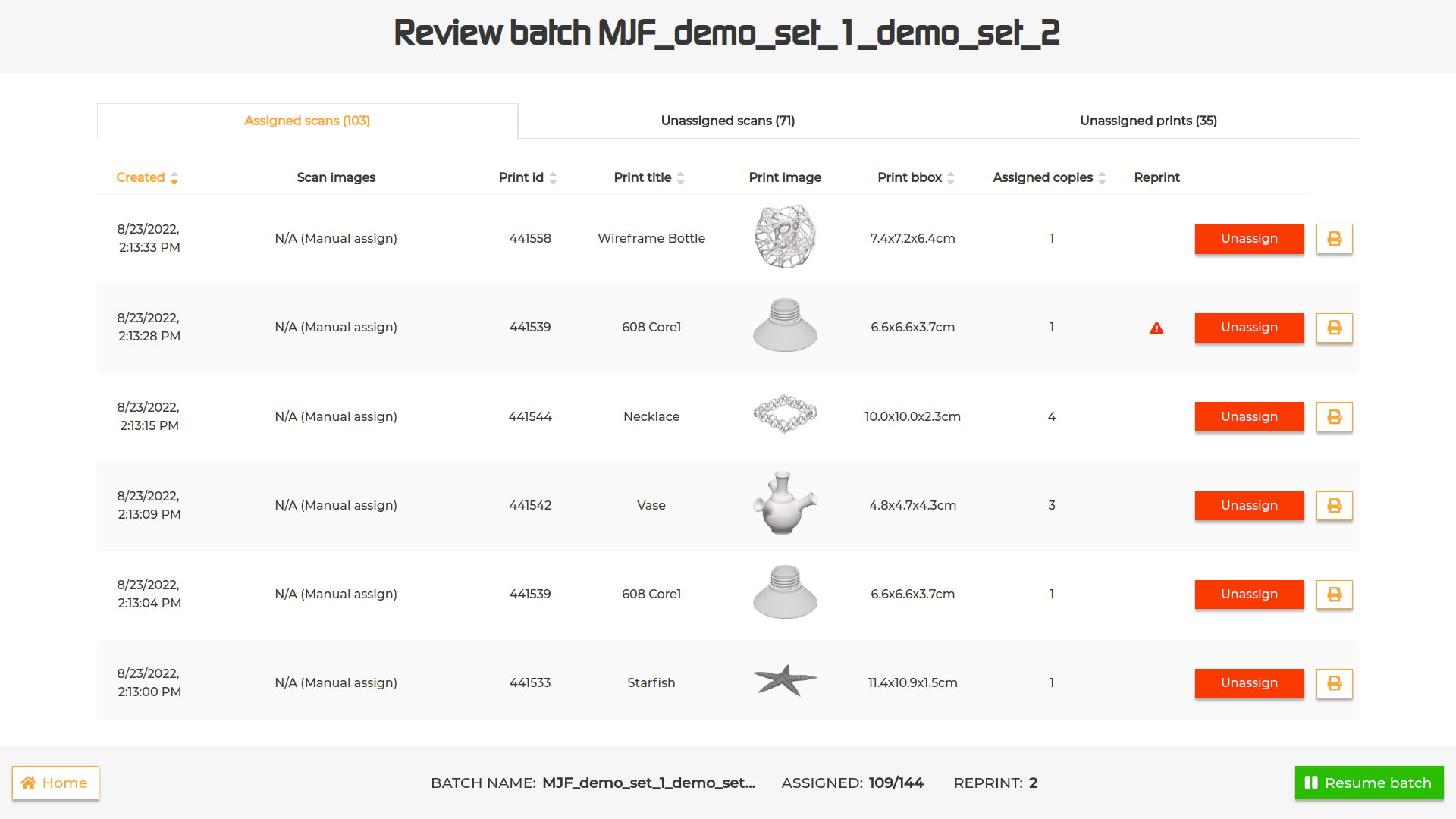
The interface displayed will show three tables:
(1)Assigned scans: a list of all the scans taken for that batch that have been assigned and the parts they’ve been assigned to.
In case of a mistake during assignment, it is possible to unassign the scan by pressing the ‘Unassign’ button. The unassigned scan will be displayed in the ‘Unassigned scans’ list. It is also possible to reprint a label for the selected assignments via the print button.
More details are available by tapping on the scan images (detail of the scan pictures), on the part image (displays part details screen) and on the reprint icon (shows reprint reasons and comment in case your system supports them).
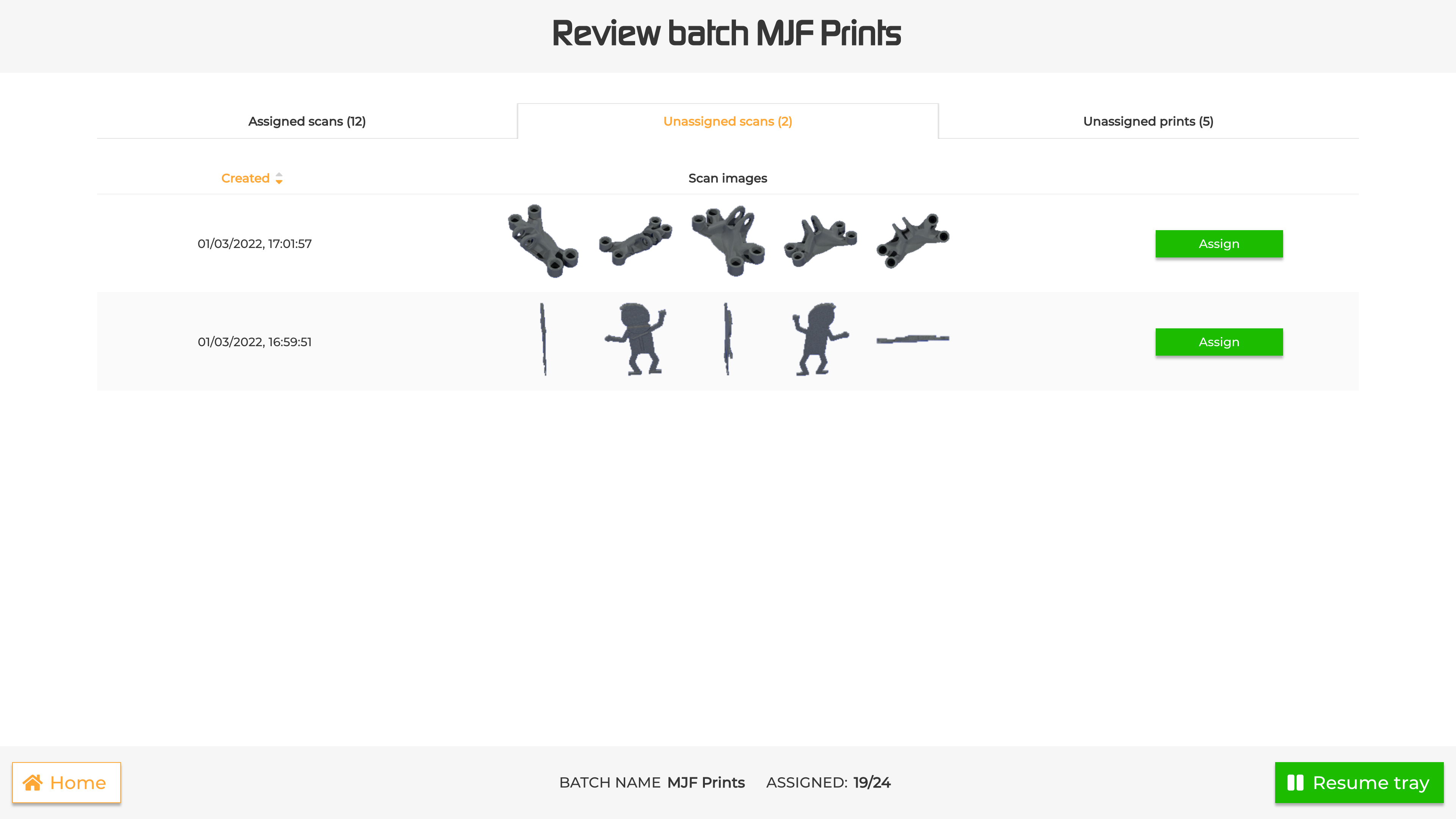
(2)Unassigned scans: a list of all the scans taken that haven’t been assigned. To assign one of them, press the ‘Assign’ button and choose the part to assign it to from the ‘Scan results’ interface that gets displayed.
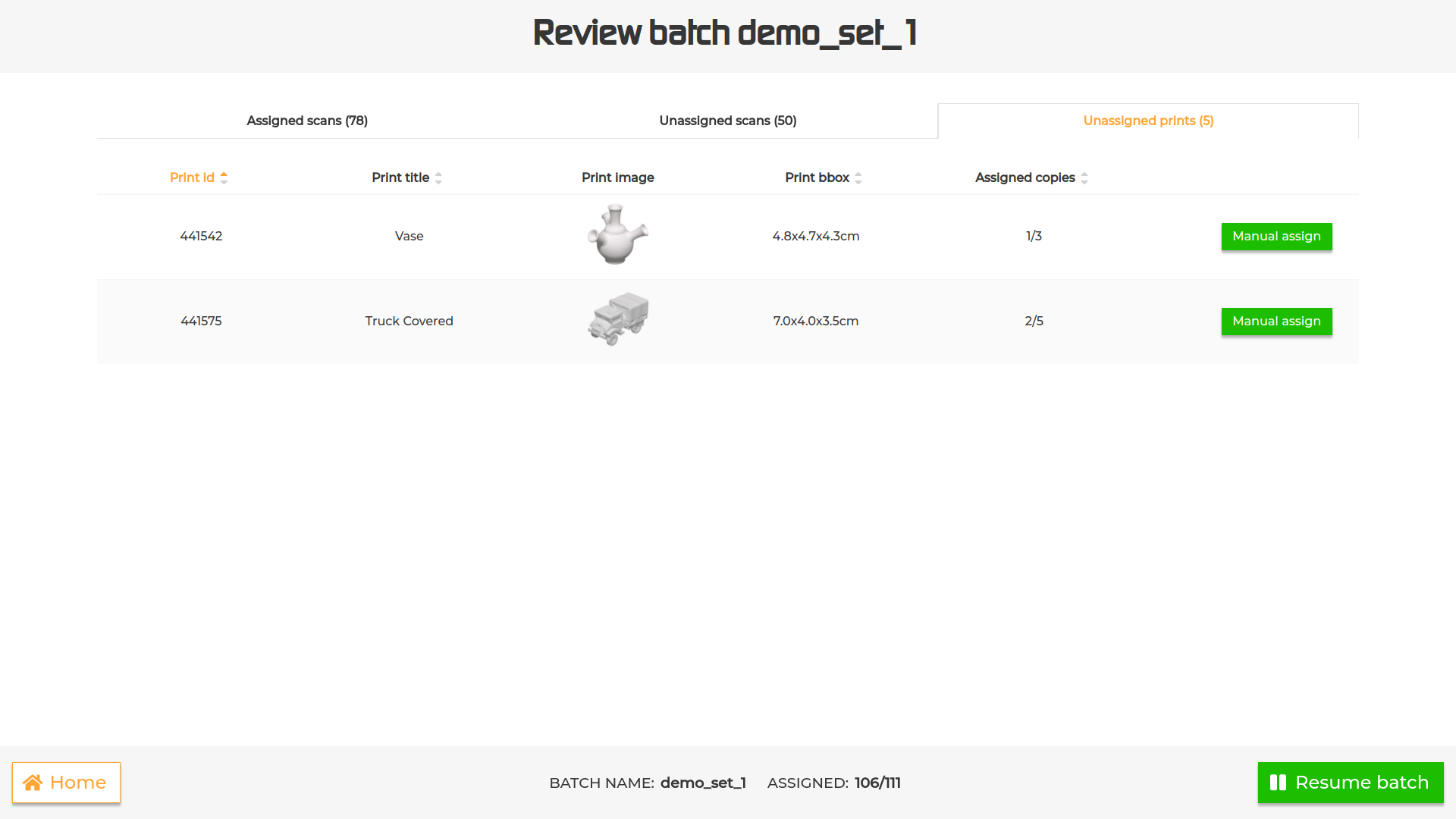
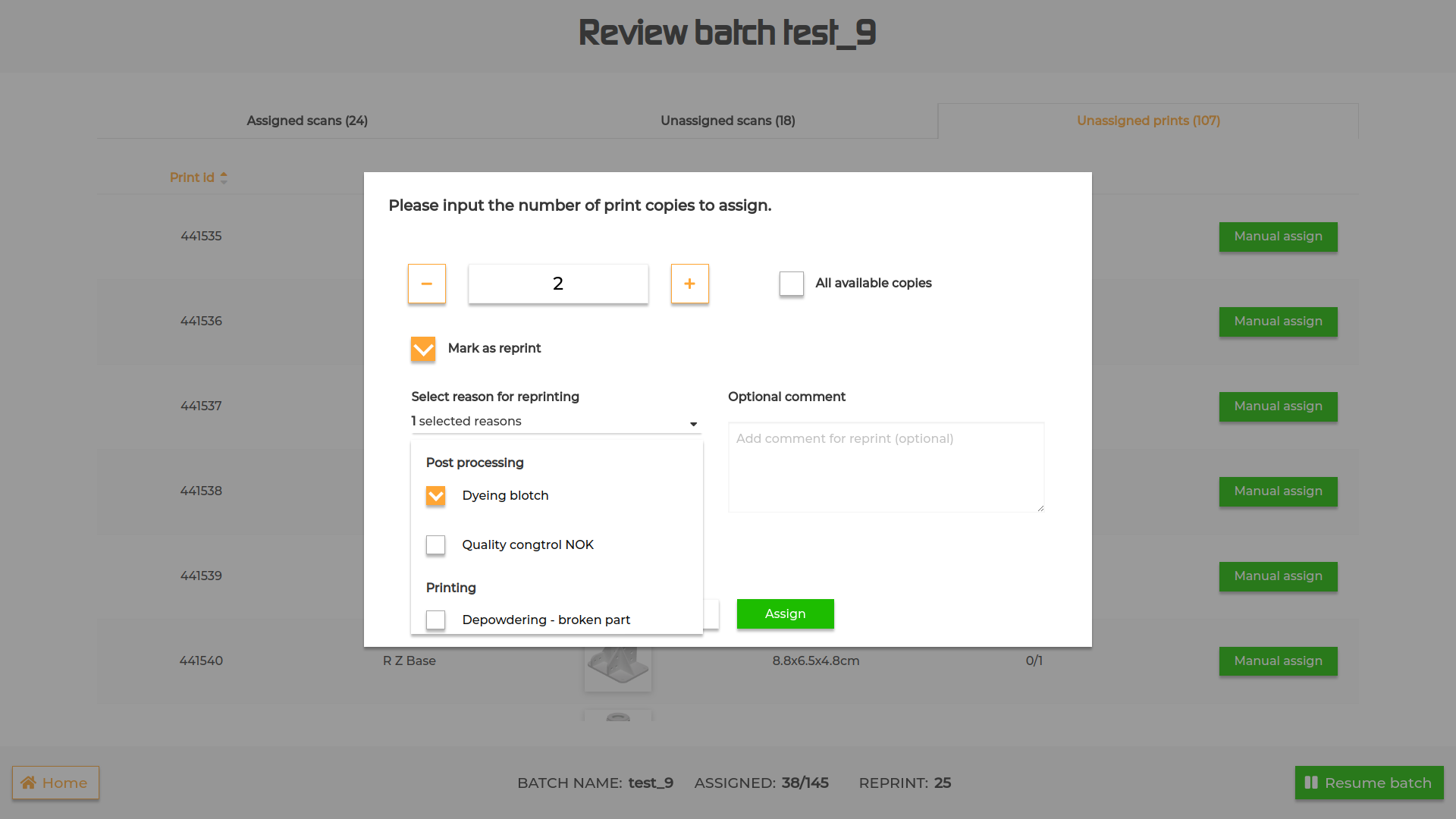
(3)Unassigned parts: a list of the unassigned parts in the batch. To assign one of them without making a new scan, press the ‘Manual assign’ button, input the amount of copies to assign and press ‘Assign’. To mark the part as a reprint, simply select the option on the popup, select the reason for reprint from the list in the dropdown (optional) and/or type a comment (optional) and press ‘Assign’.
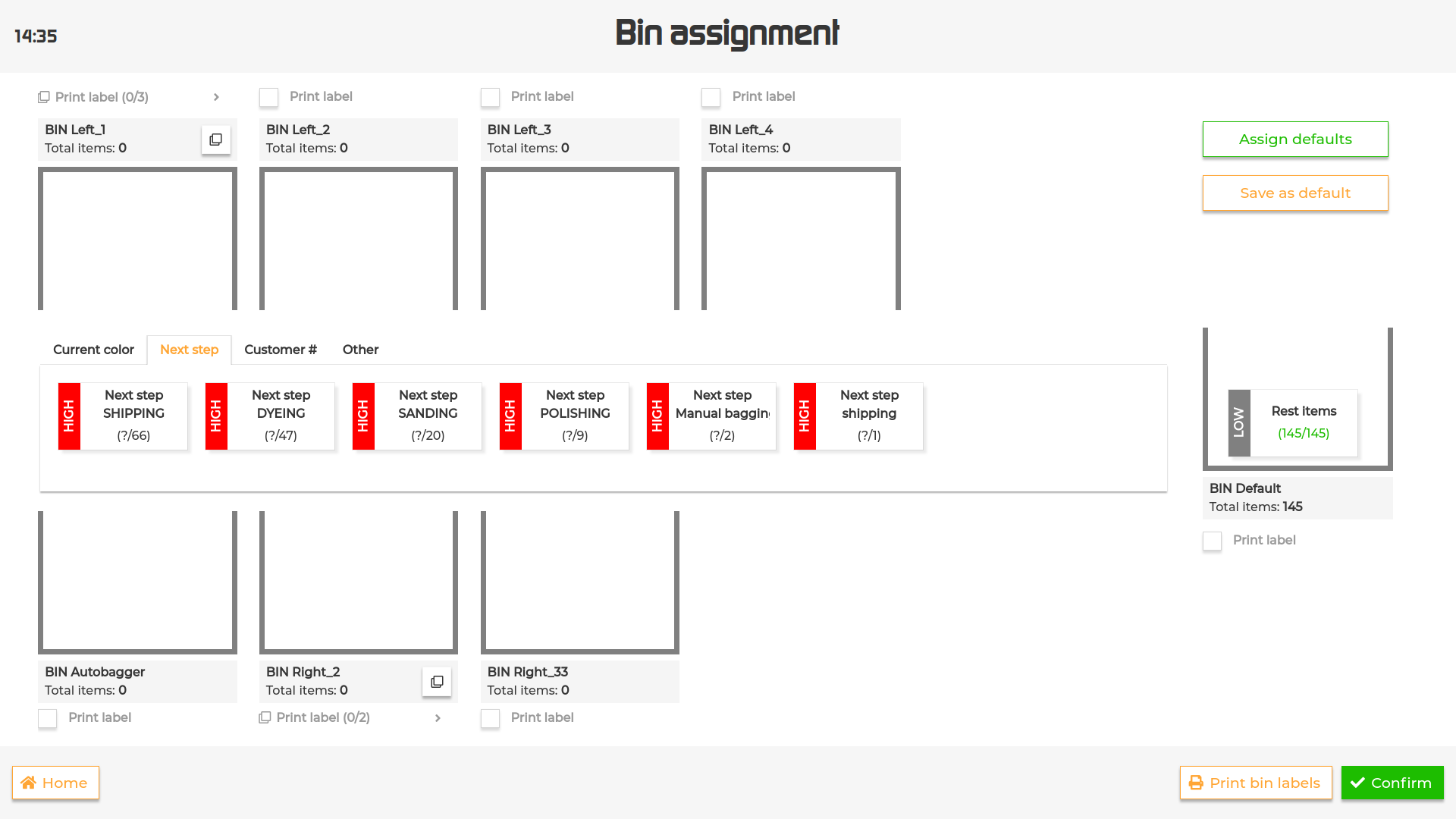
After starting a batch for the first time, the operator will be required to set how parts will be sorted after recognition.
IN the interface you can visualize:
a central container is your virtual belt with the unsorted tiles
lateral containers that represent the outputs of your machine
the ‘tiles’ in the central container are the sorting criteria. Sorting criteria can have a LOW, MEDIUM or HIGH priority and those priorities will be displayed as a lateral label on the tile. Unless set otherwise, all criteria have by default a MEDIUM priority.
After recognition, the system will look for a match between the part and a sorting criteria and sort the part in the correct output.
If a part matches more than one sorting criteria (e.g. a part matches both a next_step-SHIPPING and current_color-BLACK criteria), the part will be sorted based on the sorting criteria with the highest priority.
In case the matching criteria have the same priority, the part will be sorted based on the output order.
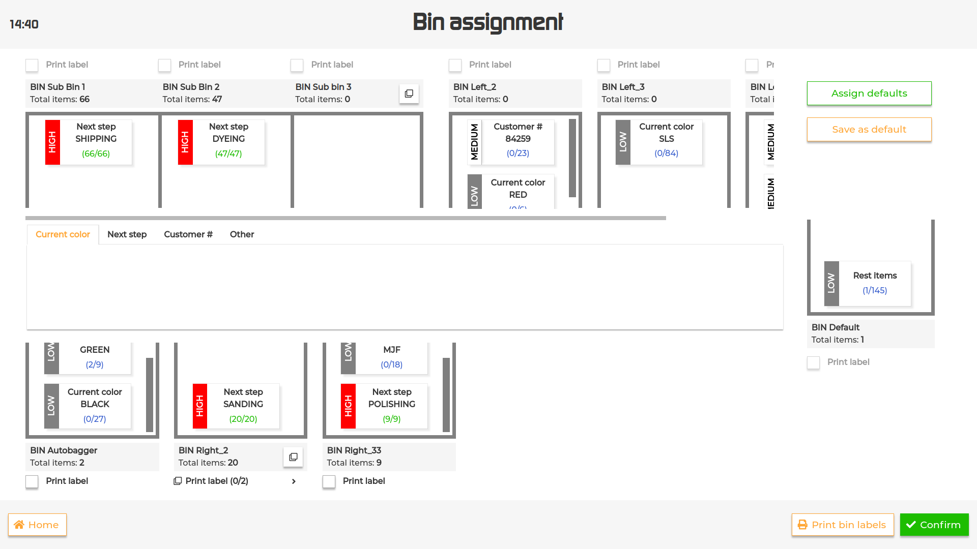
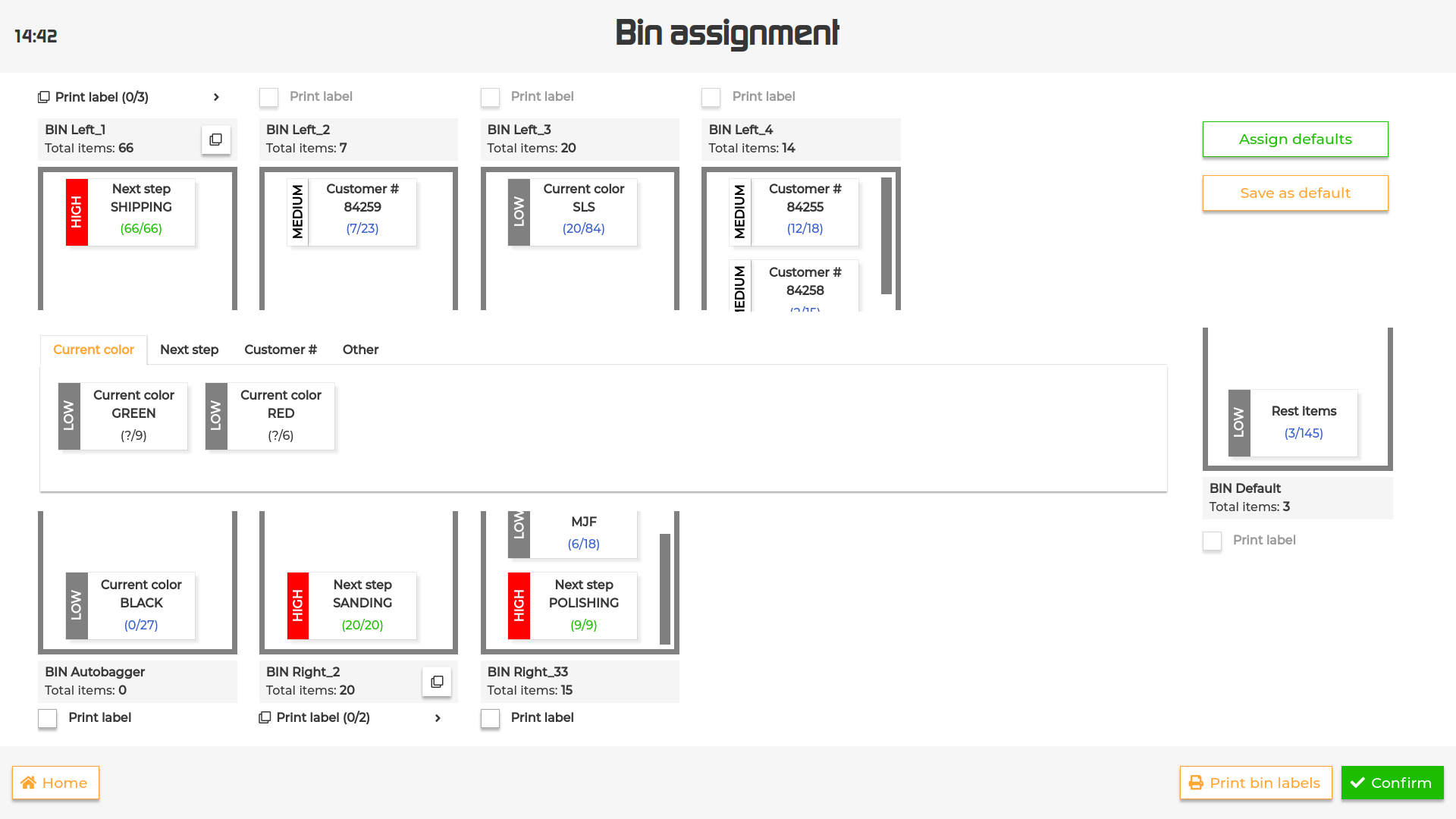
To define how parts will be sorted after recognition, simply drag and drop the tiles into the desired output.
There is a special “Rest items” tile which is by default displayed in the “Default” output. This is a placeholder that collects all the parts that don’t match any of the queries available for the selected batch and it can be used to sort the aforementioned objects to any of the outputs.
The count of matching parts per query is displayed as the number of actual parts that will be matched with the query / total of matching parts within the batch.
To save the current assignments as default for future batches, press ‘Save as default’ button.
To apply saved assignments, press ‘Assign defaults’. The defaults will be assigned on top of the already sorted tiles (if any).
The queries can also be displayed by category by selecting one of the tabs on top of the centered container.
If your system supports sub outputs, they will be displayed in an expanding/collapsing output that allows the operator to assign queries to each sub output.
It is also possible to select the “Part label” option independently for each sub output.
If the physical output has a label printer assigned, it will be possible to select the “Part label” option below/above the output to have a label printed for each object in the container.
It is also possible to print one label per output instead. In this case, after dragging all the tiles to the desired outputs, simply press the ‘Print output labels’ button in the bottom right corner.
To reset previous output assignments, go to the homepage, open the dropdown menu for the selected batch and choose the “Reset output assignment” option.
It will be possible to set new assignments after re-starting the batch.
To edit previous output assignments, go to homepage, open the dropdown menu for the selected batch and choose the “Edit output assignment” option.
Modify the assignments as you please and then press “Confirm” to save them.
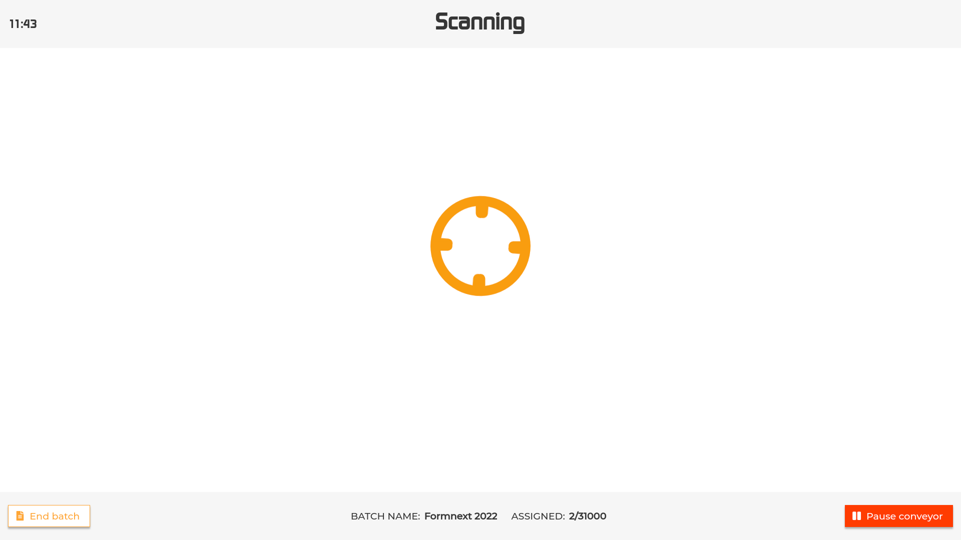
After confirming the output assignments, the machine will automatically start running and it will be possible to place parts on the conveyor belt for the recognition.
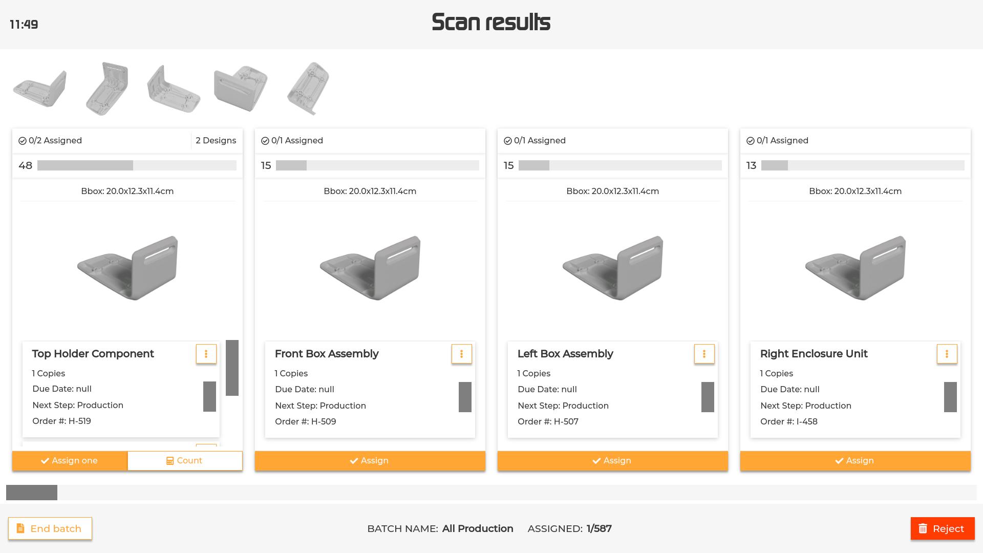
When the part is scanned, the user will be presented with a list of the parts in the batch ordered by the confidence that the machine has that the part is the one that was scanned.
Each design is represented by a card showing the following:
(1) Number of assigned parts out of total parts.
(2) Thumbnail of the part. Touch the thumbnail to display a rotating 3D model of the part and move it to examine the details from different angles.
(3) Confidence level. The matching score is expressed through a confidence level indicated by a number and a progress bar.
(4) List of parts within the group. For each part, it is indicated:
Name (Touch the screen on the corresponding area and scroll to the left to read the entire content in case of long names)
Number of copies of the part
Details (set by the customer)
If output grouping is enabled, multiple designs might be grouped in the same card. In that case the list of designs will display the same details as above.
Depending on your machine settings, the machine will:
(A) Automatically assign the part/ reject the scan and proceed to the next scan.
(B) Stop to wait for the operator input.
To assign one copy of the part to the scans, touch “Assign” in the corresponding part.
In case of wrong assignment, it is possible to replace the old assignment with a new scan via the button “Replace”. This will lead to a new interface (Conflict) that will allow the operator to remove the old assignment(s).
Assignments can also be reviewed from the ‘Review batch’ interface available during scanning. To reach the interface, press the ‘Pause conveyor belt’ displayed in between scans and then ‘Review scans’.
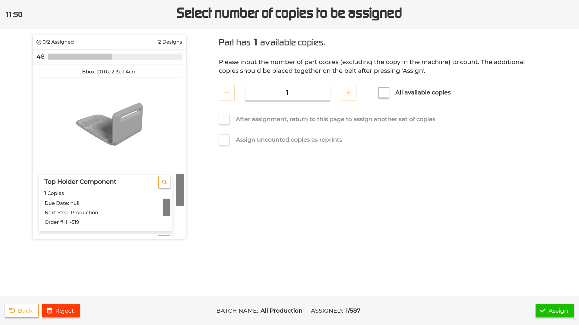
To assign multiple copies to the same scan, press “Count”. This will open a new interface.
Enter the additional copies to assign via the plus/minus buttons or the virtual keyboard (tap on the input field to display the keyboard), press the ‘Assign’ button in the right bottom corner and place the remaining parts on the conveyor belt (optional depending on your machine settings).
Select the “All available copies” option to assign all free copies for the part.
There are a few options available to decide how to handle the assignment:
(1)After assignment, return to this page to assign another set of copies: if selected, it will allow you to split the copies over multiple assignments.
(2)After assignment, count and assign next identical part: in case of identical parts this further option will be displayed and will allow you to count and assign the next identical part without making a new scan.
(3)Assign uncounted copies as reprints: allows to mark the uncounted copies as reprints. If output grouping is enabled and you selected a group, you’ll be asked to select which part you want to assign as a reprint.
If you have the integrated scale option, see Scale Integration on how to use it.
In case of damaged or defected object it is possible to notify it to the system by marking it as a reprint.
To report a reprint, open the three dotted menu in the right upper corner of the card and select ‘Reprint’. If your system supports comments on reprint, a popup will appear asking you to input reasons and additional comment for the reprint. Input these information (if desired) and press the ‘Reprint’ button to confirm.
To examine the details of the part, open the pop up menu (5) in the corresponding card and select “Info” (see Part details for more details).
To interrupt the scanning session without assigning the scan series, touch “End batch” (). This will redirect to the Summary page.
Please note that by interrupting the scanning without assignment, the unassigned scans will be automatically deleted.
To get new scans for the same object, touch “Reject”.
Please note that by rescanning, the previous scans will be automatically deleted.
To see all the objects in the batch, touch “Pause conveyor”. You will be redirected to the Summary interface.
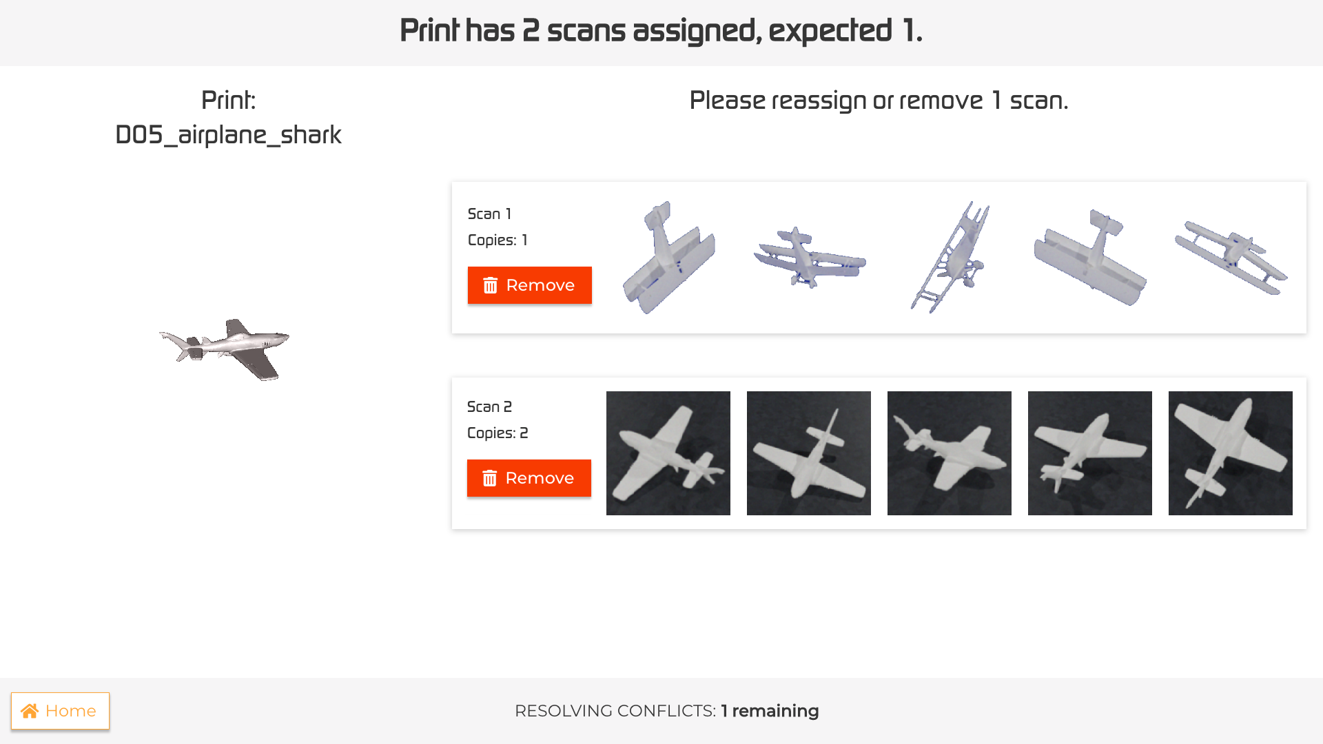
The conflict interface is displayed when the amount of assigned scans exceeds the expected amount for a selected part.
To solve the conflict, remove the exceeding series of scans by pressing the “Unassign” button.
The selected series will be displayed in the unassigned scans list in the ‘Review batch’ page and the remaining series will be automatically assigned to the part.
After solving the conflict, the scan session will be resumed.
To resolve the conflict at a later time, press the “Home” button.
The unsolved conflict will be displayed in the status of the corresponding batch. To resolve it press “Resolve”.
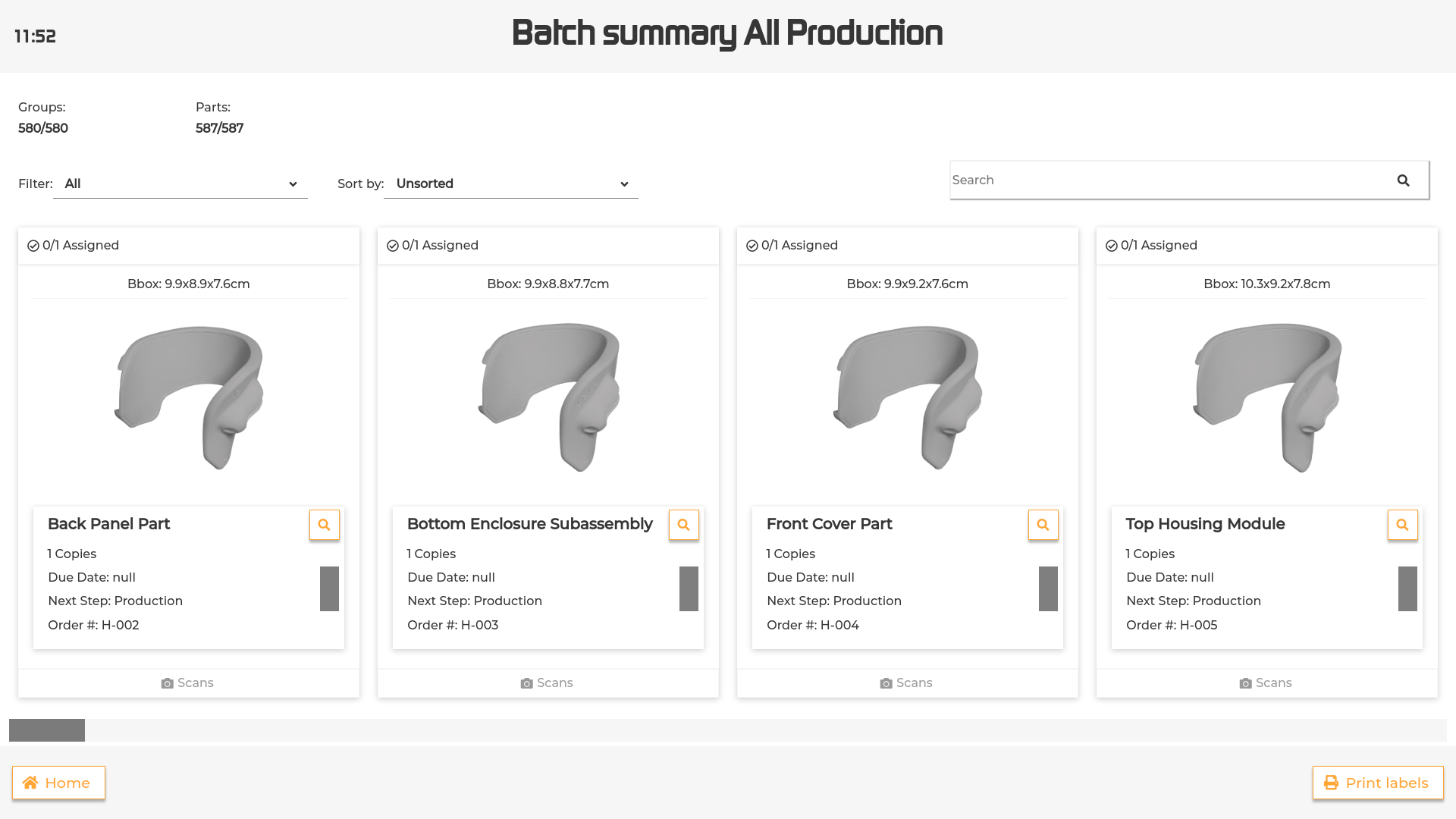
The summary interface provides a comprehensive view of the status of the objects within a specific batch.
For more details about the information displayed for each object, please refer to the Scanning page.
To examine the details of an object, touch the inspect button. This will open the Part details page (for more details see below).
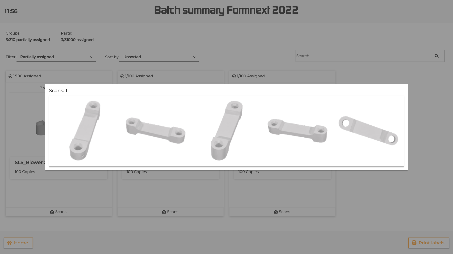
To visualize the scans assigned to a part, touch the bottom of the part’s card where the number of scans is indicated. This will open a pop up rendering the scans (see image below). Touch the dark background or the “X” at the top right corner to close the pop up.
To filter the parts by their status in the system, use the filter dropdown and select between the following options:
All: displays all the parts within the batch.
Fully assigned: displays the groups that are completed. A group is considered completed when all the parts within that group are assigned (e.g. all of the parts belonging to the group have been through the machine).
Partially assigned: displays the groups that still need to be completed, but have at least one copy assigned (e.g. one or more of the parts belonging to the group have been through the machine).
Unassigned: displays the groups that don have any copy assigned (e.g. none of the parts belonging to the group have been through the machine).
Reprints: displays the Reprints for the batch. The number of Reprints in each part is also indicated in the part card.
Conflict: displays the conflicted parts in the batch. In case of conflicts, a “Resolve all conflicts” red button will be displayed. Press the button to be redirected to the Conflict page.
To sort the list of parts, press the “Sort by” button in the top right corner, select the desired sorting parameter from the dropdown menu and use the ascending/descending buttons to change the order.
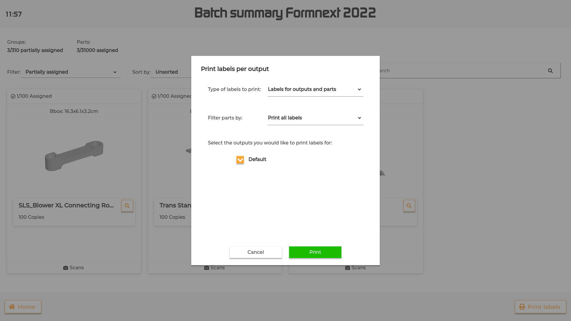
To print a collated label for one or more sorting ouputs, press the “Print labels” button at the bottom right corner.
Define the settings for your labels in the popup and press ‘Print’ to print the labels.
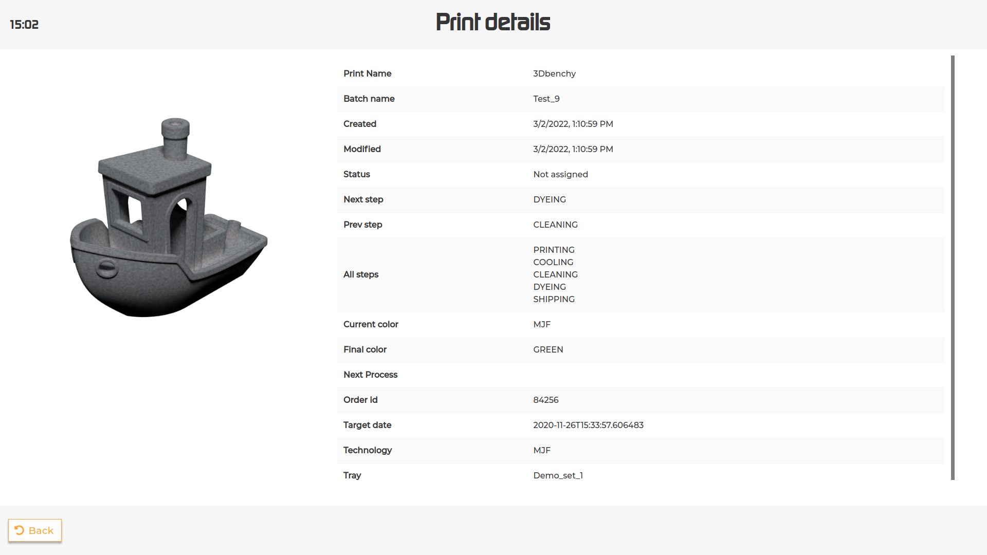
The part details screen displays the information available for the selected part. It is possible to see the rotating 3d model by tapping on the part thumbnail.
It is possible to access this page in every interface presenting the objects by either touching the inspect button or opening the pop up menu and selecting “Info”.
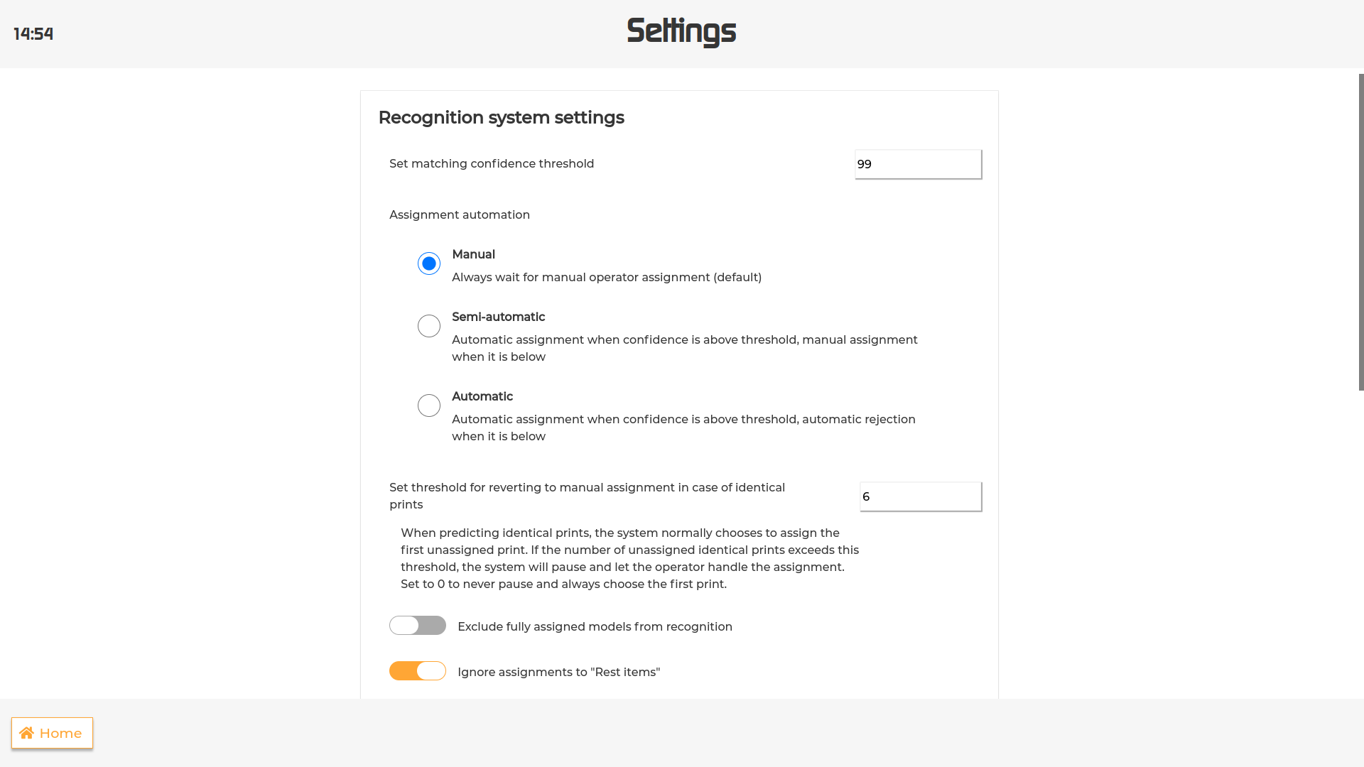
This section of the settings allows you to customize how the recognition system behaves.
The first option lets the user change the threshold above which a part is considered a match.
To change the threshold, tap on the input field, type in a value between 1 and 100 and press Confirm.
Please be aware that by setting a customized value, the default one will be permanently deleted.
To calibrate the cameras, press the “Calibrate” button. For further details on the calibration procedure please refer to the Camera Calibration paragraph below.
The assignment automation section allows the user to customize the system’s assignment behaviour by choosing one of this three options:
Manual: the system always waits for the user to either assign or reject every scan before moving to the following one.
Semi-automatic: the system automatically assigns the scan to the part if the confidence is above threshold, but pauses when it’s below to let the user assign or reject the scan.
Automatic: the system automatically assigns the scan when confidence is above threshold and rejects it when it’s below.
When in “Semi-automatic” or “Automatic” mode, the system automatically assigns the first unassigned part and pauses when it finds a number of identical unassigned parts that exceeds the set threshold.
It’s possible to customize this threshold from the Set threshold for reverting to manual assignment in case of identical parts option by tapping the input field and type in the desired value.
Set the threshold to 0 to never pause.
By default, the system will display the part/prints with the highest confidence in the “Match found” or “Top results” screen, regardless of their assignment status.
It is possible to exclude the assigned parts from the recognition process by enabling the Exclude fully assigned models from recognition option. The assigned parts will remain visible in the view all screen, but they will be ignored during recognition.
By default, assignments to parts that are to be sorted as Rest items are ignored. It is possible to change this setting by disabling the Ignore assignments to ‘Rest items’ option.
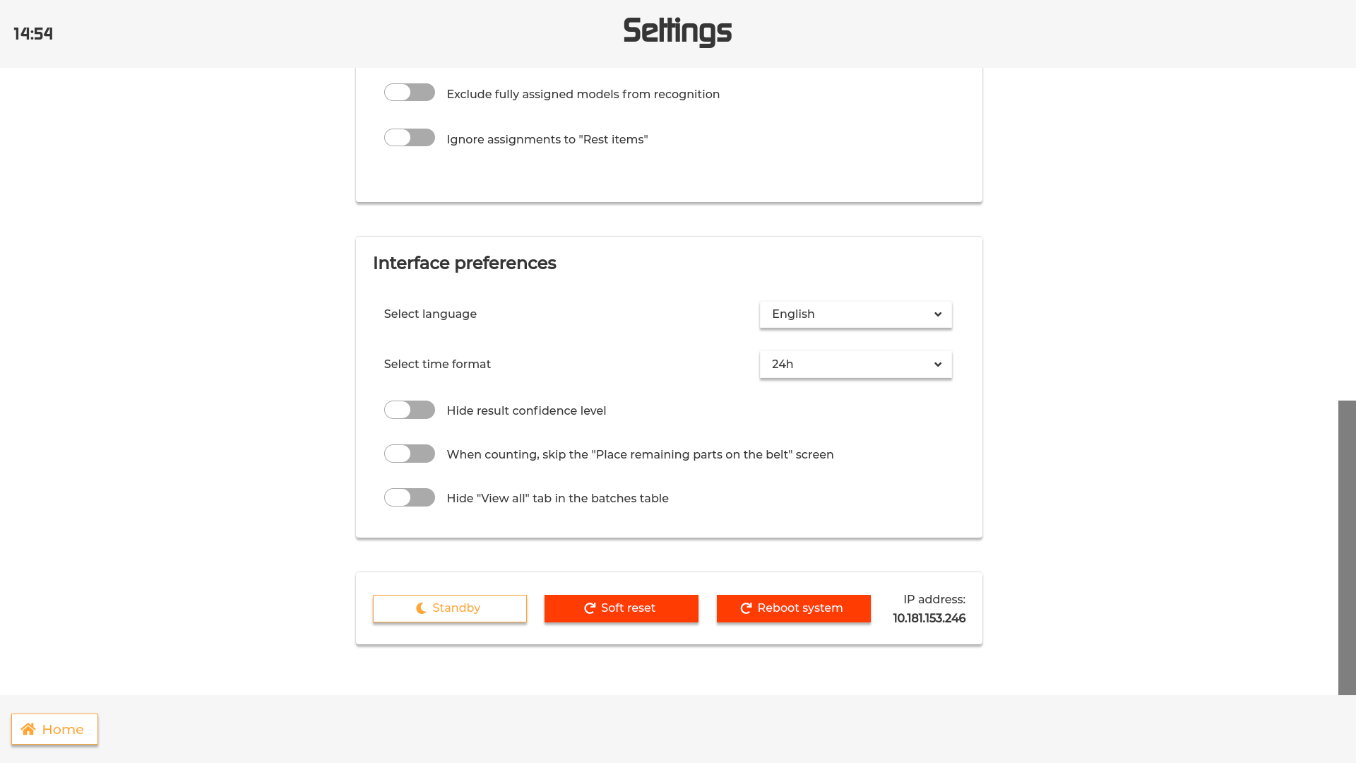
Select language: allows to change the UI language. It is possible to choose among English, German and Dutch.
Select time format: allows to choose between a 12h or 24h format for the clock on the screen.
Hide result confidence level: hides the progress bar displaying the confidence level in the Match Found and View All interface.
When counting, skip the “Place remaining parts on the belt” screen: When assigning multiple parts, this option allows to assign the desired number of copies and place the remaining parts in the sorting output without scanning them.
Hide “View all” tab in batches table: hides the “View all” tab in the homepage list.
To select or deselect one or more options, simply toggle the button.
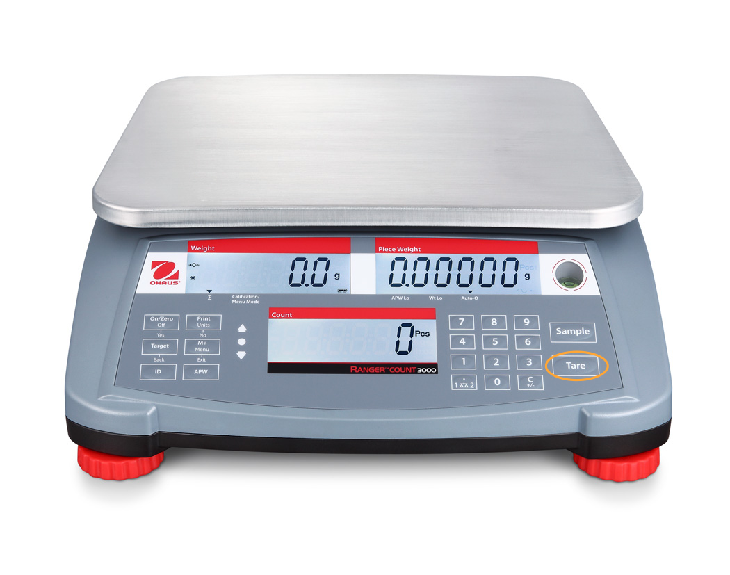
When assigning multiple parts using a single scan (see`Match Found`_) you can use the scale integration to count
the parts by weight. To do so proceed as follows:
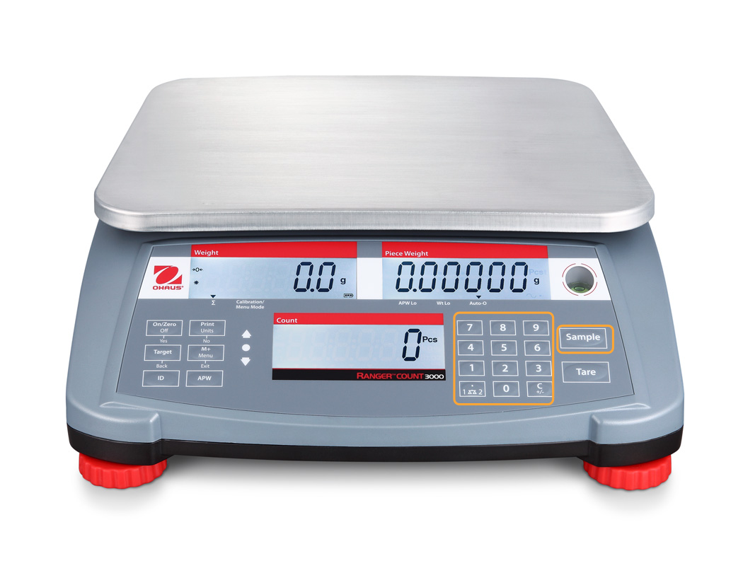
Next we need to compute the average part weight. Count and place a subset of the parts onto the scale. As a rule of
thumb, place at least 5 parts to compensate for variation in weight across the parts. Enter the count using the
digits and press “Sample”.
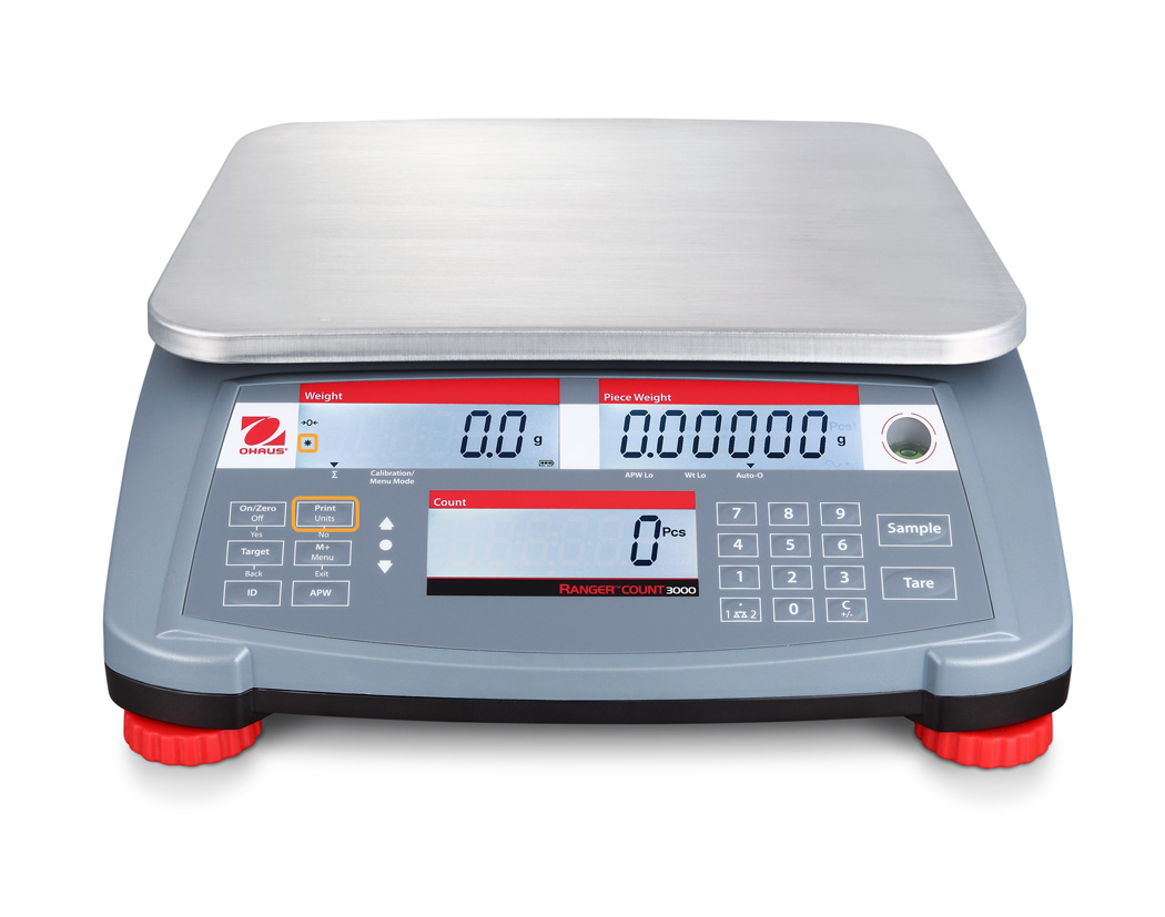
We are now ready to place the rest of the parts and send the count to the screen. Place the rest of the parts onto
the scale. Wait for the machine to become stable (as indicated by the “*” (asterisk)). Press “Print”.
The count should now be filled in on the count screen.
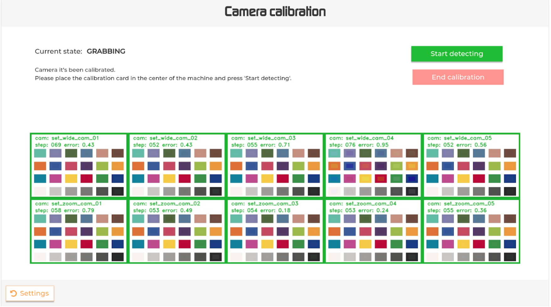
The procedure starts with detecting the calibration card.
To do that, please place the card in the middle of the machine and press the “Start detecting” button.
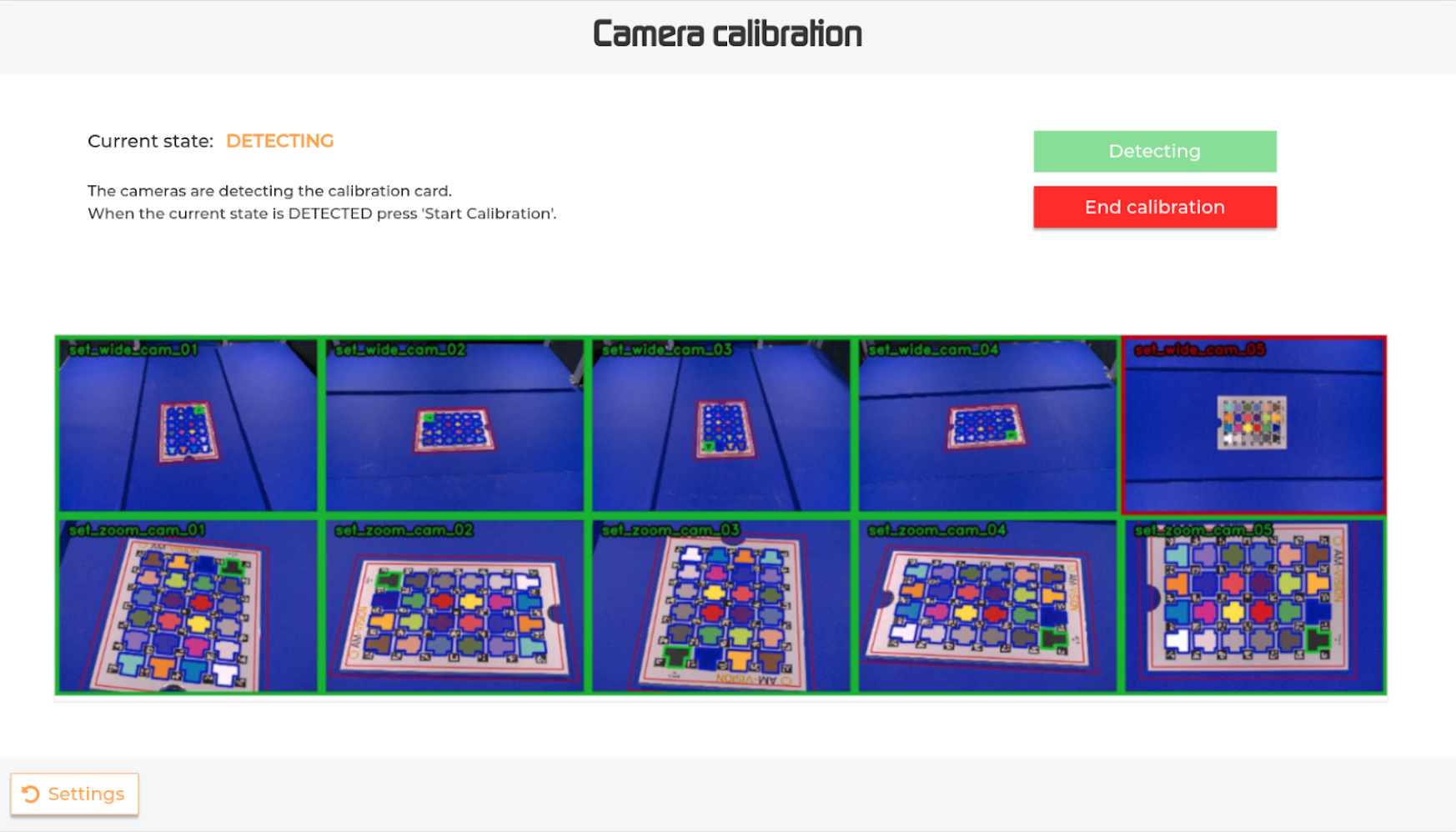
A real-time stream image will appear on the screen displaying the detection status for each camera.
The green bordered rectangles correspond to cameras that successfully detected the card, while the red bordered ones are still in the process.
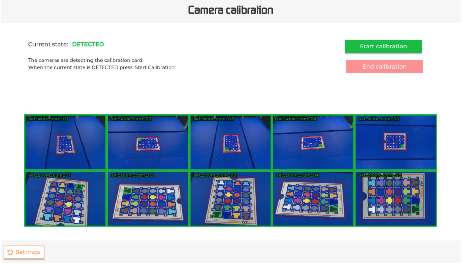
The detection is completed when the current state changes to “DETECTED”.
Please note that the state could go back to “DETECTING”. If that happens, please wait for the state to switch back to “DETECTED” in order to start the calibration.
To interrupt the detection, press the “End calibration” button.
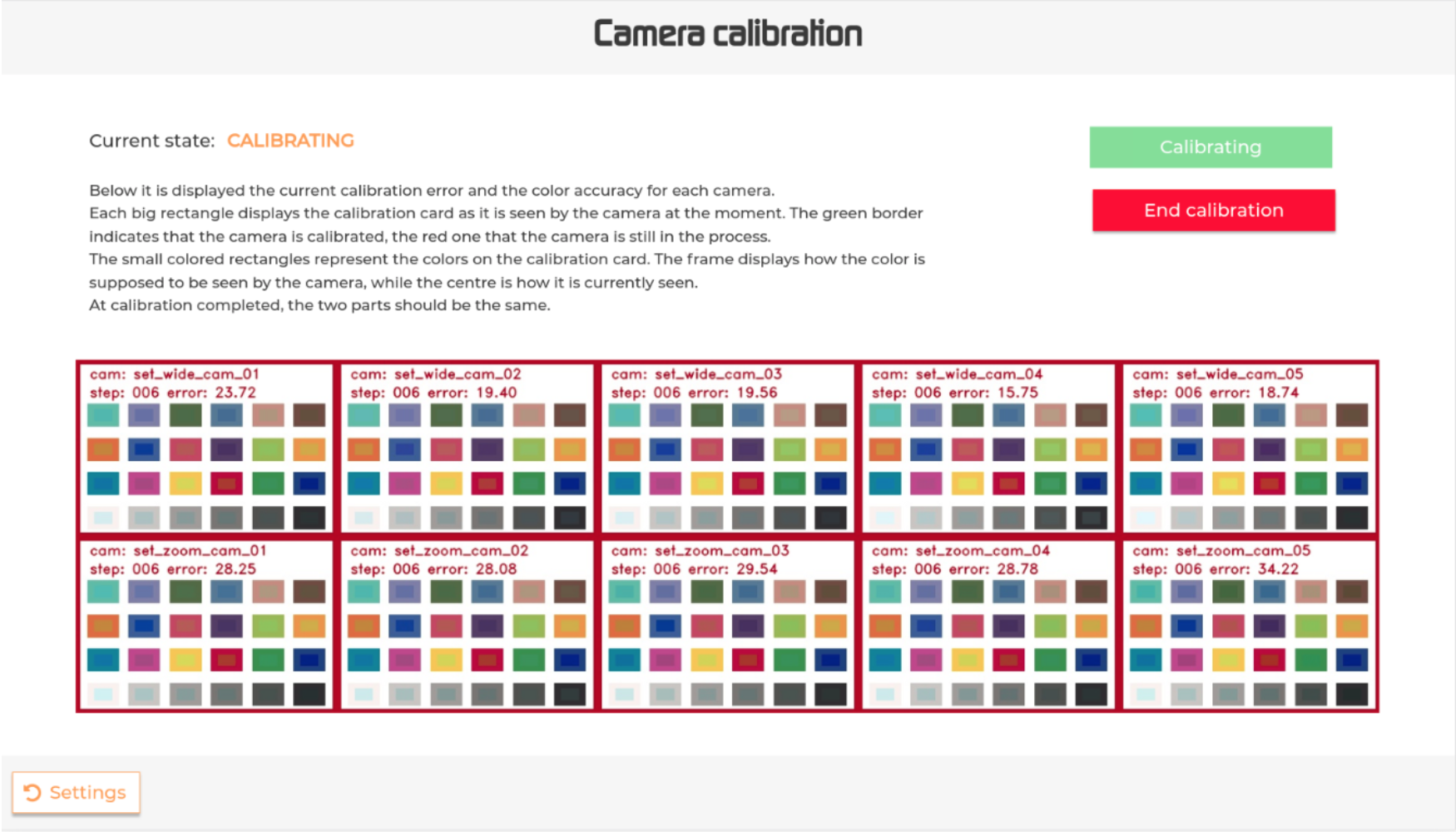
As in the detection phase, a real-time stream image will appear on the screen to keep the user informed about the progress of the calibration for each camera.
Each large rectangle displays the calibration card as it is seen by the 10 cameras; the top 5 boxes in the rectangle are the wide angle cameras, the bottom 5 boxes are the zoom cameras.
The green border of each of these boxes indicates that the camera is calibrated; the red border that the camera is still calibrating. Whilst calibrating you will see the borders of the boxes turn from red to green.
The smaller colored rectangles within each camera box represent the colors on the calibration card.
If you look closely, you will see that the center of the colored rectangle is one shade of color and the outer side is another color; the center color is how the camera should see the color, the outer color is how the outer camera currently sees the color. The calibration aims to get these two colors as close together as possible (within 1.0 error).
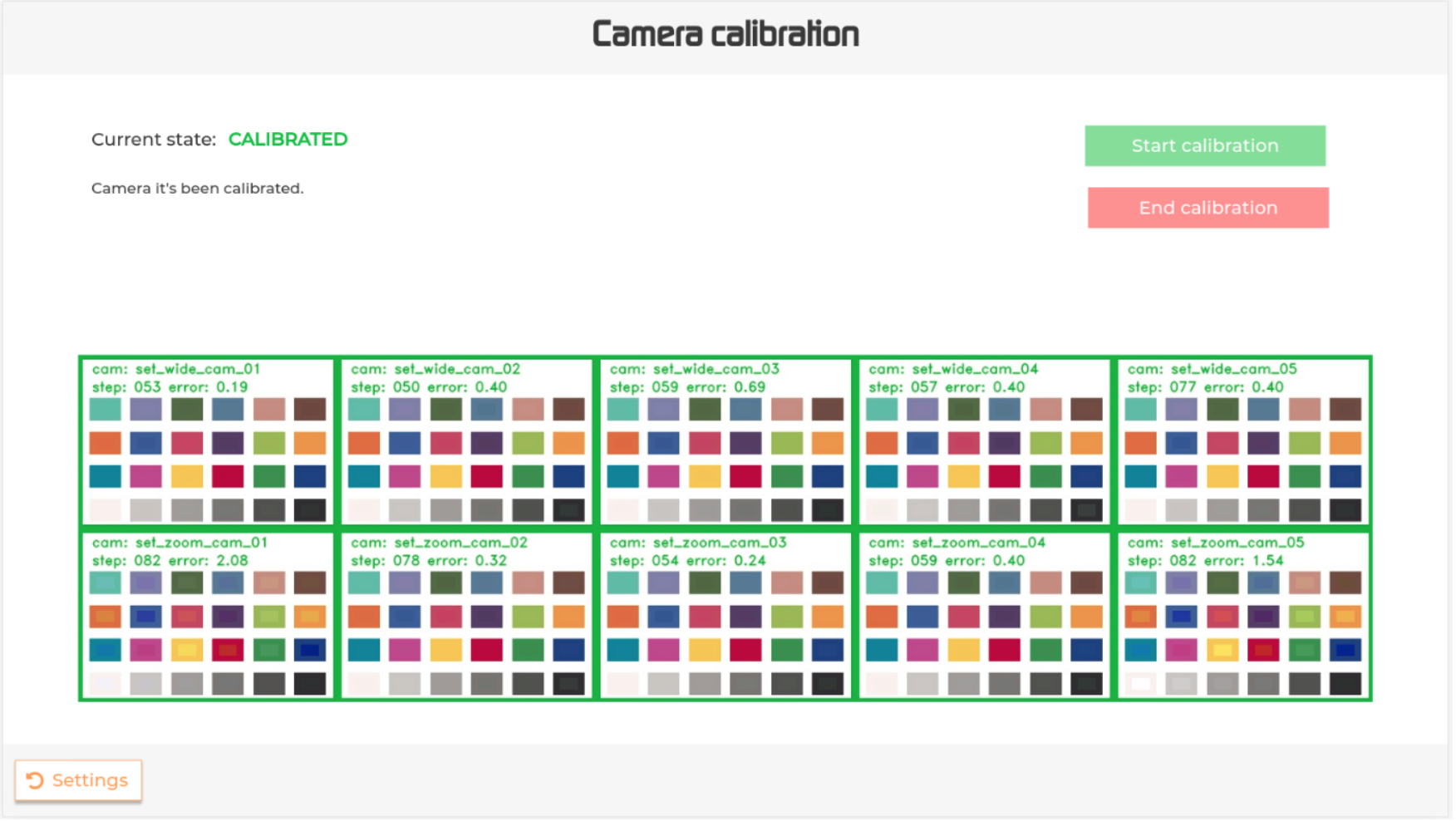
Calibration is complete once the center and outer parts are the same and the border colour of the box turns from red to green.
10. Quality inspection result (only for AM-Vision + AM-Quality systems)
You can inspect the results of the automated quality evaluation in two main ways:
While reviewing a batch (see Review batches): Each scan assignment shows whether the quality evaluation passed or failed, and whether it has been approved by an operator. A button allows you to open the inspection result directly.
From the Summary page: Each scan listed under a part includes a button to access its inspection result
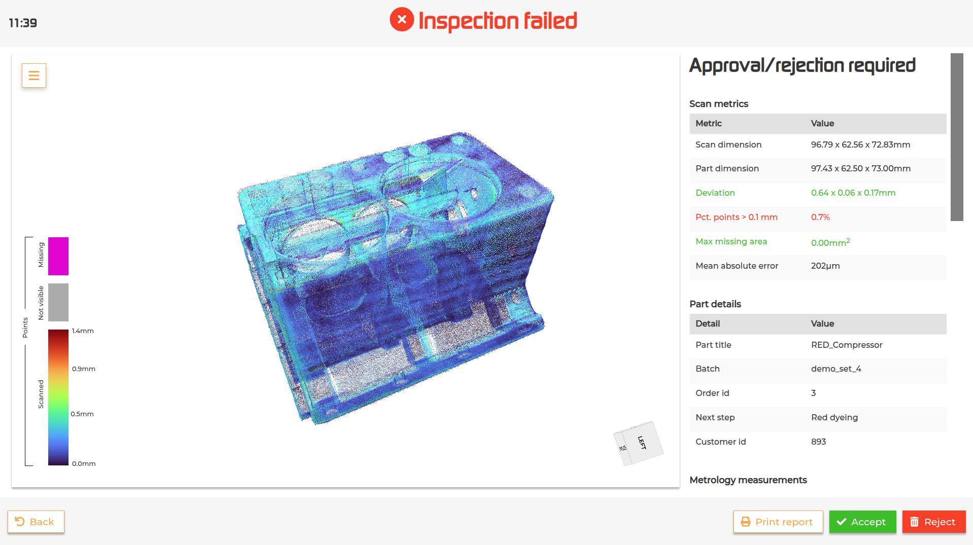
The inspection result page provides a 3D visualization of the scanned part, detailed information about the scan, the part and the metrology measurements performed during the evaluation (if a metrology template for that part was available).
The side menu on the visualization gives you control over how the data is displayed. You can choose to view just the scan point cloud, the original part design, or both overlapped. You can also switch between orthographic and perspective views, and select a color scheme for the pointcloud: a simple green/red pass-fail display, or a full colormap that highlights the range of deviations across the scan.
Additional display options can be toggled on or off, including:
Bounding boxes for the scan and the part
Highlighting the point with the maximum deviation
Showing the largest missing area
Enabling a full deviation-range colormap (the colormap used by default applies its range of colors up until the distance threshold, so every point that has a deviation above the distance threshold will be red. This options allows you to apply the colormap to the full range of deviations)
Adding distance labels to a representative set of points
Switching to a colorblind-friendly colormap if needed.
If metrology measurements are available, tapping any row in the measurements table will overlay that specific measurement directly onto the 3D visualization.
From this page the operator can accept or reject the result and can also print a report (if supported).
Each sorting output comes with a display showing the content of the output.
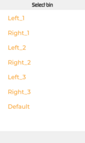
On the first setup of the display, the user can select the desired output from a list of all the outputs available.
After choosing the output, the specific output screen will be displayed.
It is possible to change this setup at any time by touching for a couple of seconds the output title in the top left corner of the screen and selecting a new output from the outputs list.
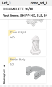
The screen of the selected output will display useful information during the scanning process (number of parts in the output, number of expected parts, assigned sorting criteria).
It will also show a list of parts divided into three dynamic sections:
(1)Unassigned: a list of all the parts in the batch that match the sorting queries assigned to the output and are expected to be sorted into it. Because parts can match more than one sorting queries, this list might include parts that will be sorted in another output and will be updated accordingly.
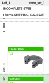
(2)Belt: a list of parts that have been scanned, assigned and will be sorted in the output, but are still on the conveyor belt.
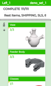
(3)Output: list of parts that are in the output at the moment.
It is possible to display the information on the screens also outside the scanning process by navigating to the Summary page.

).
 ) and select the “Combine batches” option.
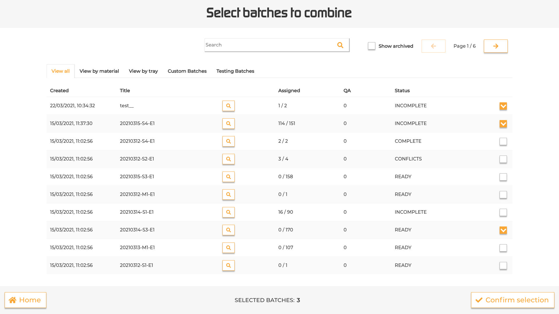
 ). This will redirect to the Summary page.